Robot Dog Frame

Skills: SolidWorks, Mechanical Design, 3D Printing, Laser Cutting
The Robot Dog Frame project aimed to redesign the robot's frame with the goal of optimizing the structural integrity and functionality of it. The redesigned frame achieved a large weight reduction while enhancing the practicality and durability of the frame.

Objective

During my time as the Mechanical Frame Lead at the NU Robotics Robot Dog club, I was the sole person responsible for redesigning the previous existing frame into a smaller, lighter, and more efficient version. The redesign also had the goal to optimize material usage, preserve key elements of the previous design, and enhance the robot's overall performance and adaptability for various applications. The following image shows the CAD for the previous robot.

Design Process

Rods

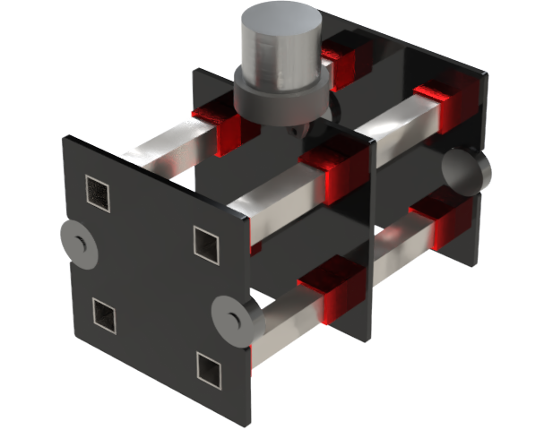
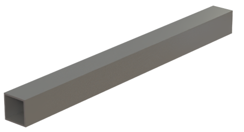
The initial step in my design process was to determine which materials and concepts from the previous iteration should be retained. A key decision was to repurpose the square, hollow aluminum rods, measuring 2x2 inches, as the main structural components of the frame. Made from 6061 aluminum, these rods offer an excellent combination of properties, making them ideal for the application. With a density of approximately 2.7 g/cm³, 6061 aluminum ensures the frame remains lightweight. Its tensile strength of up to 310 MPa and yield strength of 276 MPa provide outstanding durability, allowing it to withstand significant stresses without deformation. Additionally, with a modulus of elasticity of about 69 GPa, this material offers the necessary elasticity to effectively absorb dynamic loads. These qualities ensure the rods maintain the structural integrity of the frame while contributing to a lighter, more practical design. These rods will also be shorter in this deisgn as to make the robot more lighter.
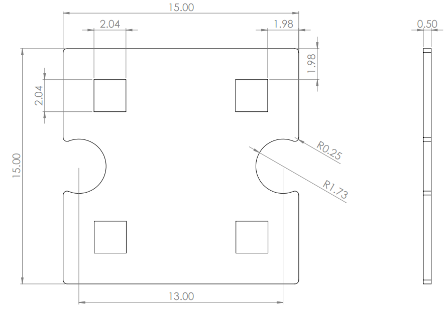
Body Plates

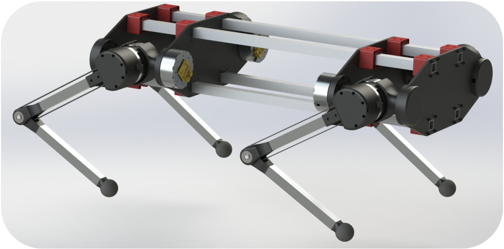
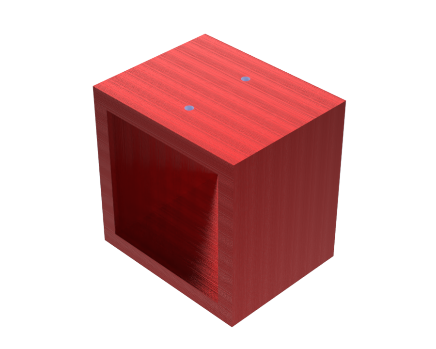
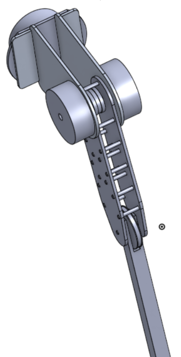
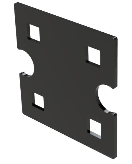
The frame plates of the robot dog are designed to be constructed from acrylic, chosen for its excellent mechanical properties, its affordability, and ease of manufacturing. Acrylic offers sufficient stiffness and strength for the application, with a tensile strength of approximately 70 MPa and a lightweight structure that nicely complements the aluminum frame. This material was also chosen, as we had already selected laser cutting to be our main manufacturing method due to its precision, speed, and availability, making it significantly easier than machining or 3D printing other materials. The design consists of three plates: a front plate, a back plate, and a middle plate. Both the front and back plates feature circular cutouts to house two motors each, facilitating direct attachment to the robot’s legs. The middle plate, while identical in other respects, lacks these cutouts, serving as a structural component to provide additional rigidity and stability to the frame. The following images show the CAD of the front/back plate and its mechanical drawing.
To secure the acrylic plates firmly to the frame, aluminum brackets are employed as a fastening solution. These brackets are designed to fit snugly over the square aluminum rods, and screws are used to tighten the brackets, ensuring that the acrylic plates remain securely in place during the robot’s operation. This fastening method ensures precise alignment of the plates, enhances the overall structural integrity of the frame, and allows for easy assembly and disassembly of this frame, without the need to glue of solder the parts.
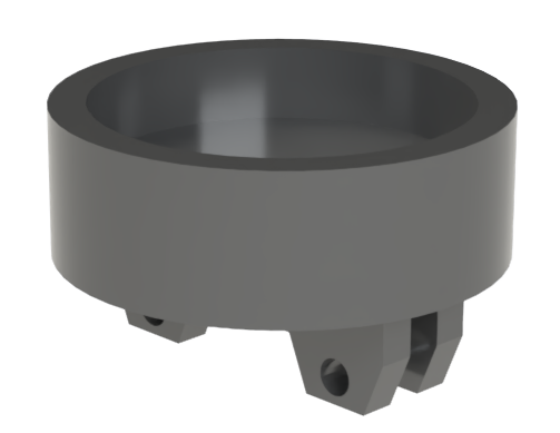
LiDAR Sensor Holder

For navigation, a 3D LiDAR sensor will be mounted on top of the robot frame using a custom-designed holder. The holder will be 3D-printed from PLA for its lightweight and durable characteristics, and it is designed to be securely screwed into the top of the middle acrylic plate. To attach the LiDAR sensor, threaded inserts will be embedded in the PLA holder, allowing screws to align with the sensor's mounting holes. This setup ensures a strong connection while enabling easy removal and adjustments for the sensor. The holder’s design also ensures the LiDAR has an unobstructed field of view during navigation.

Motors and Legs

The T-Motor U8 V2 KV85 brushless motor was chosen for its efficiency, power-to-weight ratio, and precise control, making it ideal for actuating the robot dog's legs. Each of the four legs will have three of these motors, one for the hip joint, one for the knee joint and one for the adduction movement. This motor provides a maximum continuous current of 23A and operates at a voltage range of 6S to 12S, delivering consistent torque for smooth and responsive leg movements. It has a low KV rating of 85, which allows for excellent control at lower RPMs, which is critical for precise and stable leg positioning. The motor is also lightweight (205g) which ensures minimal impact on the overall weight of the robot, maintaining agility without compromising power. The motor attached to the frame will be responsible for the adduction movement of the leg while the other two motors will be attached to the leg itself.
The robot dog's upper legs, designed by a separate team, are constructed using lightweight yet sturdy aluminum sheets. These sheets are cut and shaped to form the structural components of the legs, which are then bound together using small metal rods to ensure durability and flexibility under load. The lower legs are made out of a similar aluminum rod as the frame. The use of aluminum provides an excellent balance of strength, low weight, and resistance to wear, making it ideal for the dynamic demands of a robot dog. For the feet, squash balls are used due to their elasticity and grip provide shock absorption and traction. Both motors are attached to the top joint of the leg with the knee being connected to the motor with a belt system. All these different parts ensure the legs complement the frame's design, contributing to the robot's overall functionality and performance.

Final Frame and Future Steps

The final frame design for the robot dog represents a well-balanced combination of lightweight materials, structural integrity, and practical functionality. The aluminum rods and brackets, acrylic plates, and 3D-printed LiDAR holder collectively form a robust and efficient framework to house the motors and support the leg mechanisms. With the design phase now complete, the next steps involve transitioning to manufacturing and repurposing. The team will fabricate and assemble each part of the frame, including laser-cut acrylic plates, 3D-printed components, and modify aluminum rods, while collaborating with the leg design team to integrate their assembly to ours. This phase will also involve testing and refining the assembly to ensure seamless operation and adaptability. The successful completion of manufacturing will lay the foundation for advancing the project into system integration and field testing.