Brainstorming
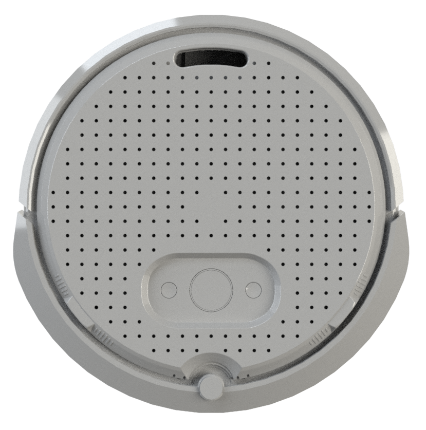
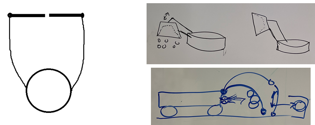
Our team brainstormed various robot designs, with each member contributing a concept. The first image (left) shows a Roomba with two arms and a gate to trap balls. The second image (top right) features a crane-like design with a dome for ball handling. The third image (bottom right) shows a dome with a fan for pushing balls towards the goal. While these were promising ideas, they were either incomplete or too complex for our timeframe and budget.
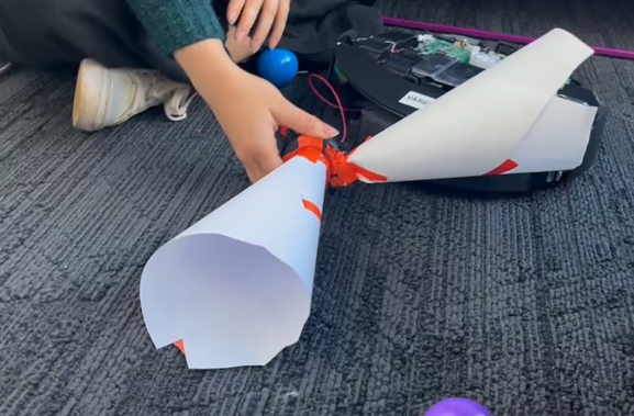
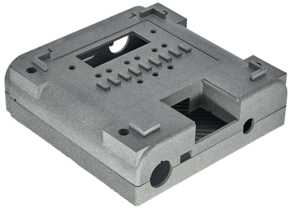
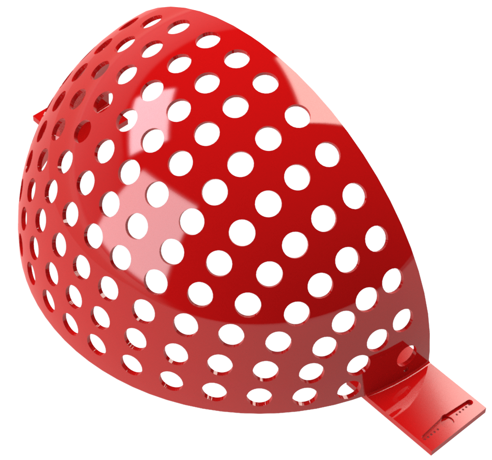
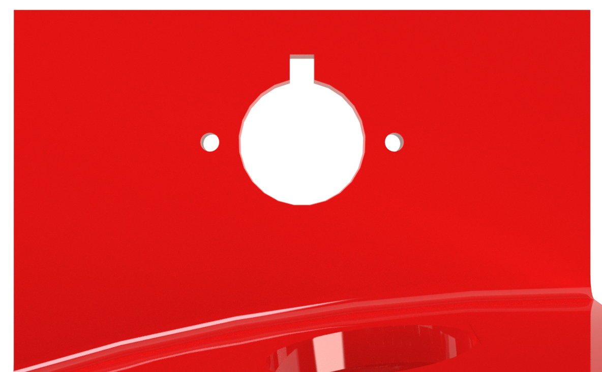
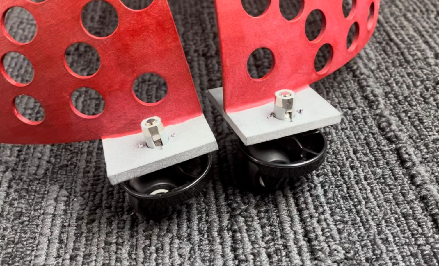
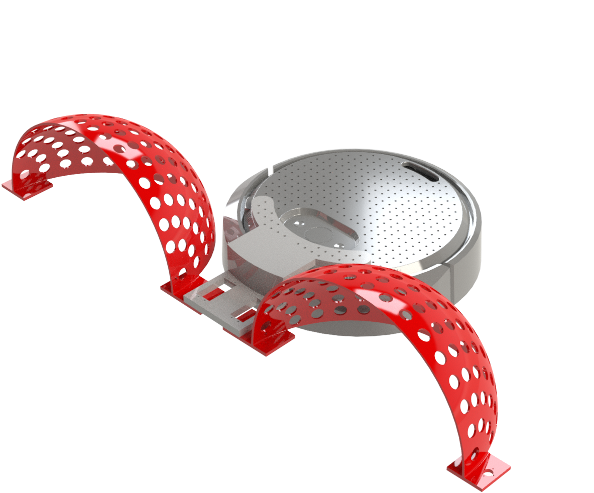
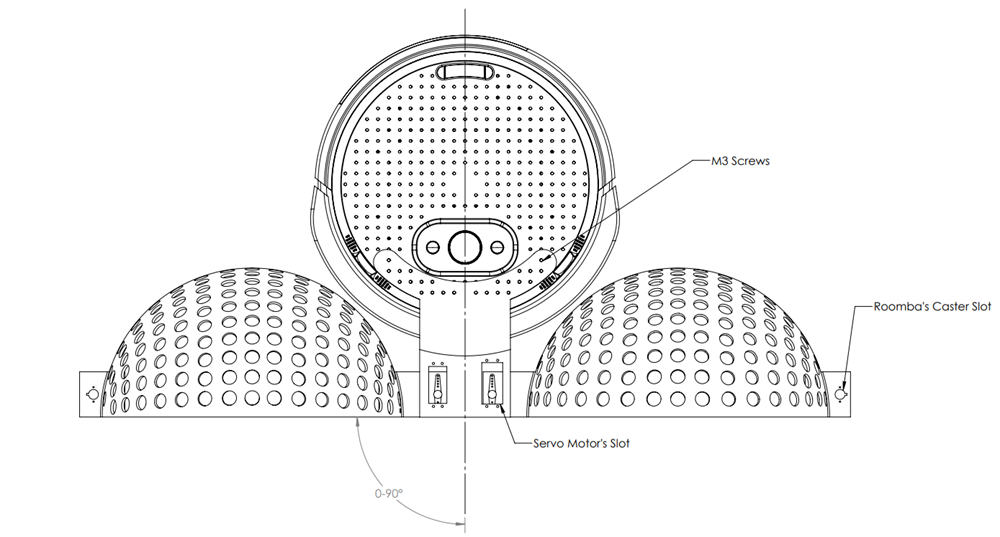
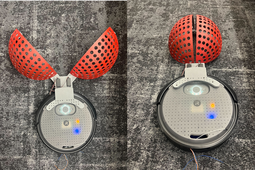
We considered all these initial ideas and also explored using the Roomba's vacuum motor to suction balls from the arena and blow them out in the goal region. Initial tests, shown in the image, involved attaching a sheet of paper to the motor. The results were disappointing—the motor could only suck in balls that were nearly touching the paper, and increasing the funnel size would have required a larger, costly motor beyond our $50 budget. After this testing, we decided to proceed with the dome idea, modifying it to open sideways with two servo motors instead of rotating.
Electrical and Software
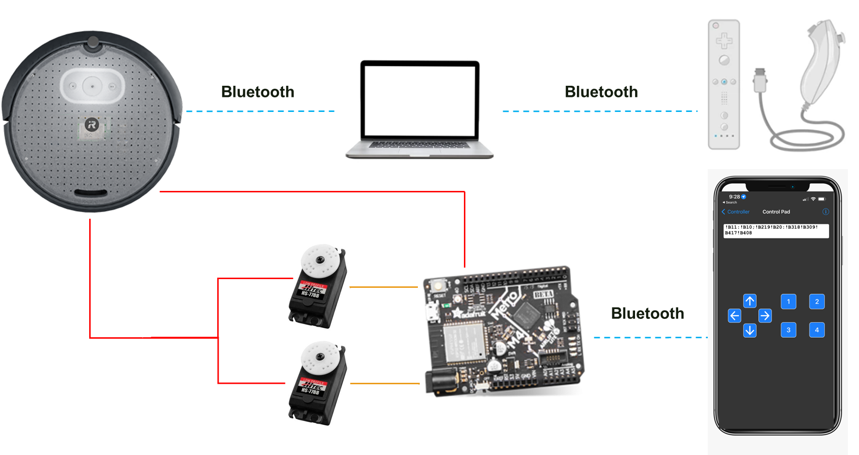
The servos were connected to an Arduino board that was then connected to the Create 3's battery to be used as the servo's power source. To control the servos, our electrical engineer decided to connect the Arduino to a phone app called Bluefruit Connect, where she could program what each button on the app did to the servos. The movement of the robot was done using a Wii remote controller that was connected to a computer that was itself connected to the Create 3 and through the use of ROS2 and other SDKs, our computer engineer was able to map the controller's button to our movement's needs. You can see a connection diagram from our robot, I will then go into more detail about each connection. The image on the right shows a connection diagram from our robot, and I will go into more detail about each connection in the following paragraphs.
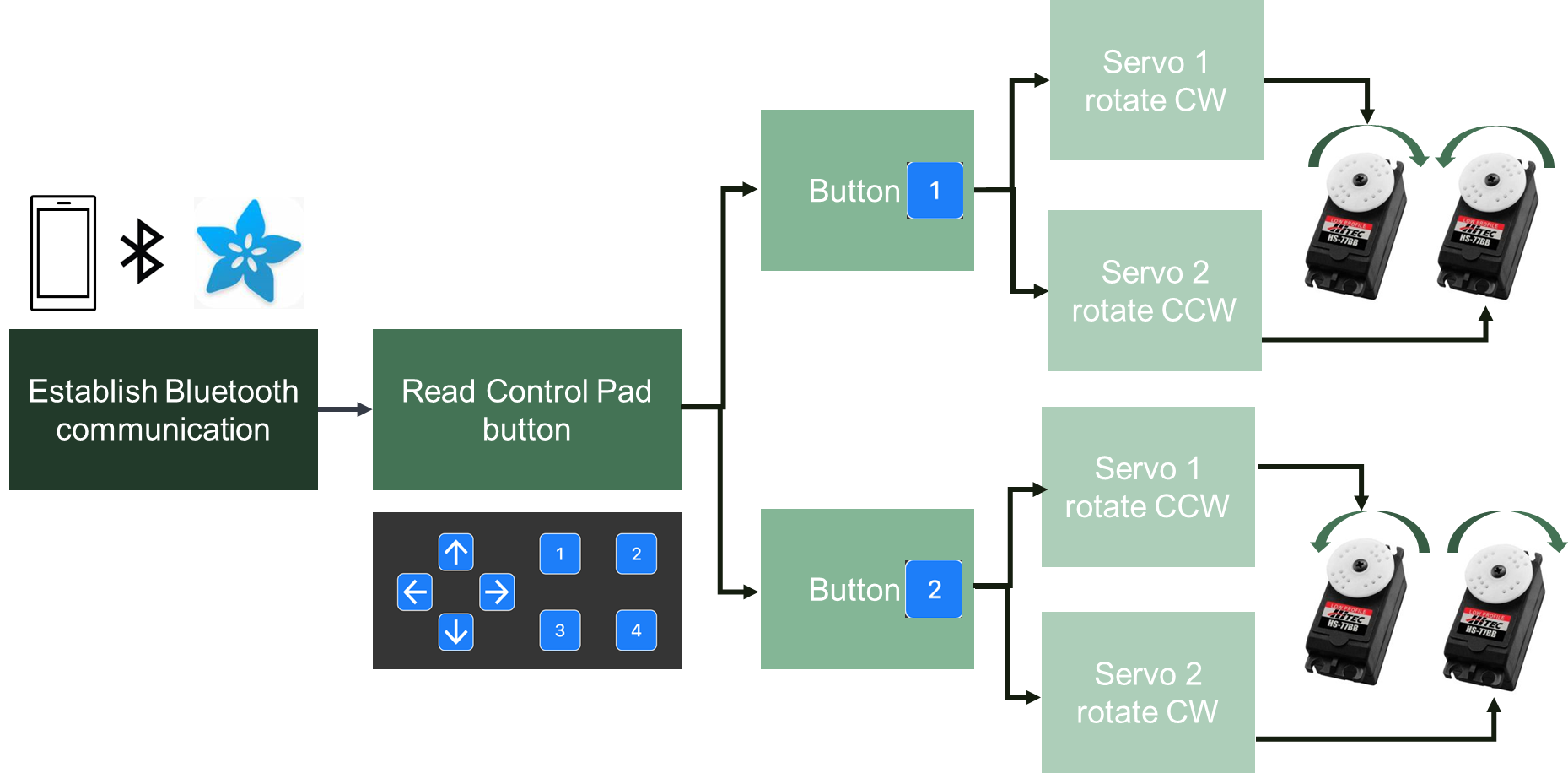
The application's layout was simple but effective. We noticed that if we wanted to open or close the dome, both servos needed to rotate in opposite directions simultaneously. To open the dome, we pressed button number 1 on the app, which would rotate the left servo counterclockwise (CCW) and the right servo clockwise (CW). To close, the user would press the number 2 button to rotate both servos in opposite directions. The image on the right shows a simple diagram of how this layout works.
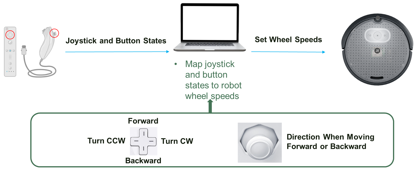
The controller connection was more complicated as our computer engineer had to overwrite the Create 3 safety limitations using ROS2 commands first. After that was done, he had to map the controller to the robot's movement. The way it was mapped is very intuitive and allowed the robot to do more complicated movements, such as rotating CW or CCW on its own axis without moving out of place, which was a crucial addition as it made our ball-gathering job much easier. The image on the right shows how we decided to map the robot's movement.