DLP 3D Printer Calibration

Skills: SolidWorks, 3D Printing, Mechanical design, Arduino, Data Analysis, UV Light Sensor
An ongoing Capstone project that aims to use a UV light sensor to measure the output light intensity across various sections of a DLP 3D printer. This project is in progress and will be finshed before May of 2025.

Objective

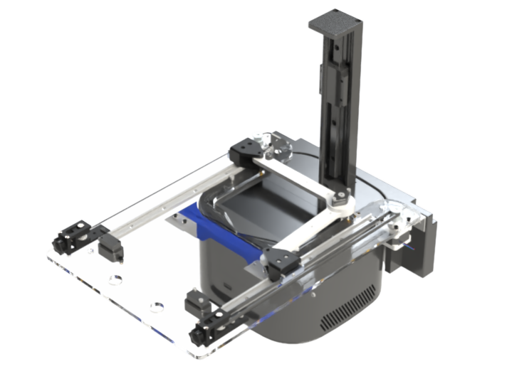
The goal of this Capstone project is to develop a fully automated system for measuring and calibrating the light intensity of a DLP 3D printer. Using a UV light sensor mounted on an automated mechanical fixture, the system will collect light intensity data across various sections of the printer. The gantry will use inverse kinematic arms to move the sensor and collect the data. The data will be processed through a Python script to generate a grayscale image, which will be overlaid with the DLP output to enable precise calibration. This process aims to ensure consistent light distribution and improved printing accuracy.

Gantry

Arm

The inverse kinematic arm is made from Delrin 2700 NC010, which was chosen for its high durability, low friction, ease of machinability, and low cost when compared to metal. The two arms will be joined together at one end, while the opposite ends will be attached onto the movement rail using sleeve bearings, as to ensure a smooth motion. The joint where the arms connect will also house the photodiode sensor responsible for data collection. An FEA analysis was also performed for the arm deflection to better assess the z-position of each arm in relation to the printing bed as to not damage it. The following images show the cad for the arm and the FEA deflection analysis results.

Movement

The movement of the gantry is done by two NEMA 14 stepper motors, which are connected to timing belts to ensure a precise motion. Each of these belts are linked to a slider that is mounted on a one-dimensional low-friction rail, while also being attached to one end of the inverse kinematic arms. To maintain optimal belt tension, a light-duty adjustable tensioner is added at one end of the belt. This setup ensures an extremely accurate positioning of the system, which is crucial for our calibration goals. One of the ends of each rail also includes a limit switch that is used to first center the fixture and prevent any unwanted movement. The following image provides a close-up view of the movement system for one of the motors.

Mounting

Gantry

The mounting plate is made of durable polycarbonate, and it serves as the foundation for the entire gantry system. Designed for an easy integration with the ELEGOO Mars 3 printer, the base attaches to the printer using existing screw holes, ensuring a stable and reliable setup without the need for any further modifications. Additionally, the mount features a UV shield, also constructed from polycarbonate, with a UV-protective sticker affixed to its interior surface. This shield helps to minimize outside exposure to UV light, protecting both the user and any person that could come in contact with the fixture. The following images show the base plate and UV casing respectively.

Sensor

The sensor mount is screwed into the top arm of the gantry, providing a stable platform for precise data collection. The photodiode is positioned approximately 1 mm above the screen, to ensure accurate measurements. To prevent any potential damage to the screen, the end of the mount features a donut-shaped microfiber pad that remains in constant contact with the surface. This pad not only protects the screen but also dampens vibrations, ensuring the sensor remains stable during operation. The sensor's wire connections will run through the center hole of the fixture and then along one of the arms. The following image shows the sensor mounting system.

Electric Work

Sensor Selection

The S5973-02 photodiode was selected as our light intensity sensor due to its high spectral response in the 405 nm range, which aligns with the wavelength of the UV light used in the DLP printing process. Its compact size and lightweight design make it a great choice for gantry integration that doesn't add any unnecessary stress. Additionally, compared to a full-fledged photosensitive sensor, the S5973-02 is significantly more affordable and easier to implement while still providing reliable and precise measurements. The following images show the photodiode and its spectral response curve.

Sensor Circuit

The sensor circuit was designed to ensure an accurate low-noise signal from the S5973-02 photodiode. Initially, our design consisted of connecting the photodiode straight into the Arduino Uno, but after some research and consultations with electrical engineer mentors, we refined the circuit to improve its performance. An AD8656 op-amp was used to reduce the noise of the 3.3V reference, ensuring a clean signal to the photodiode. In order to accurately convert the photodiode’s small photocurrent into a readable voltage signal, we incorporated a transimpedance amplifier using another AD8656 op-amp. This amplifier is important since the raw output of the photodiode is a low current, which would be difficult to measure directly and therefore requires amplification. The circuit converts the output current into a proportional voltage, allowing the Arduino’s analog input to accurately read the data. The following image shows the circuit diagram.

Motor Controller Circuit

The motor controller circuit uses the TB6600 stepper motor driver to interface the Arduino with the stepper motors to ensure a reliable motion control. The stepper motors require a 10V power supply, which is why the TB6600 was chosen, as it allows for proper voltage regulation while handling the necessary current. The controller features two key digital inputs: one for setting the motor direction and another for controlling the actual rotation. These inputs are connected to and Arduino Uno's digital ports and are managed through an Arduino code. The following image shows the motor controller circuit schematic.

Coding

This Arduino code controls two stepper motors using the TB6600 driver while simultaneously logging photodiode sensor data to an SD card. The motors move according to predetermined positions stored in a CSV file on the SD card, with each position being the arm's position in the vertical rail relative to its initial position, in millimeters. The code reads these positions, converts them to steps based on the stepper motor's step resolution, and moves the motors through digital control signals for direction and stepping. After reaching each position, the system records data for five seconds, filters out outliers, calculates an average reading, and logs the results in a separate CSV file.

Conclusion

This project is still in progress and it is planned to be completed in mid-April 2025. We are currently finalizing the manufacturing of the parts and circuits and starting to assemble our first prototype!